Cavity Walls in mid-rise and high-rise construction have proven to be successful. Even buildings exceeding 40 stories have utilized cavity walls with a structural concrete frame.
Methods of Supporting Exterior Brick Wythe for Cavity Walls
Supporting the exterior brick wythe for cavity walls cladded to concrete frame structures can be achieved through two methods:
- Shelf Angles: This method involves using shelf angles to support the brick directly on the slab edge. However, it creates a continuous horizontal break within the cavity, obstructing the vertical flow of moisture. If not detailed and installed properly, it can lead to issues such as moisture infiltration, efflorescence, and brick spalling. Moreover, a higher number of horizontal expansion joints are required when using shelf angles.
- Direct Bearing: An alternative design approach is to eliminate shelf angles and bear the total weight of the brick on the floor slab edge. This method avoids the potential problems associated with shelf angle design. However, it should be noted that thermal bridging through the exposed edge of the concrete slab can reduce energy efficiency and make this system outdated.
Considerations for Self-Supporting Brick Design
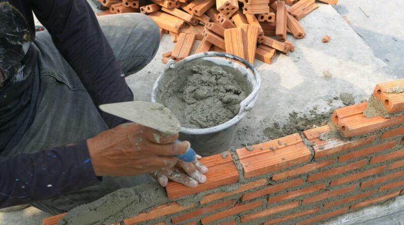
In recent years, many architects and structural engineers have opted for self-supporting brick designs, eliminating the need for steel shelf angles. However, before implementing this design, several considerations must be taken into account:
- The brick should be self-supported by the concrete foundation walls.
- The backup system should involve non-combustible construction, such as cast-in-place concrete wall panels or concrete masonry infill.
- Window spacing should be regular and not excessively large or non-repetitive to avoid irregularly concentrated loads on the brick veneer. Adjustable joint reinforcing or ties are necessary to accommodate thermal and moisture movements.
- Limited windows on the exterior of the building should be anchored to the concrete block backup system, not the brick veneer. Additionally, proper expansion joints should be detailed around the enclosed windows.
- Vertical expansion joints with recommended widths of 3/8 to 1/2 inch at 30 feet on center should be incorporated.
- The cap of the building must allow for the expected vertical movement of the brick.
- Over time, the mortar holding these self-supporting bricks together may deteriorate, necessitating remedial works such as repointing or a more decorative technique known as tuck pointing.
Additional Considerations and Limitations
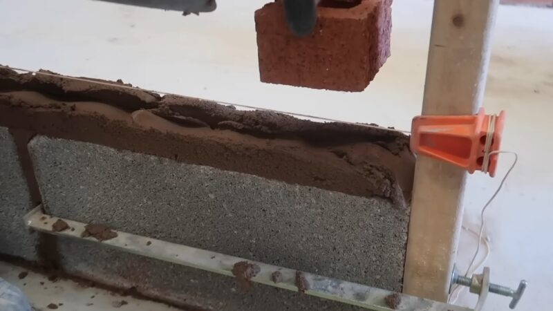
It is essential to understand the limitations and potential risks associated with self-supporting brick systems:
- The self-supporting brick system should not be applied to brick veneer/steel stud systems. In case of a fire, melted steel studs could compromise the structural stability, leading to safety concerns and falling masonry. It is recommended to use shelf angles at every floor in such systems.
- If the building occupancy changes or the use of the building is revised, the structural engineer should be aware that modifying the exterior facade may require careful execution due to the wall system’s design.
Shown here are some applications and wall sections for consideration. To ensure the longevity and performance of the system, it is crucial to install the drainage plane, flashing, and weep holes correctly, along with incorporating horizontal soft joints to accommodate frame shrinkage and masonry’s thermal expansion. –


